Pressure Independent Control Valves

BrassDN15-25PN25ISO 228-1 (BSPP) internal thread

GF-PICV-02

Pressure Independent Control Valve

Two-way pressure independent control valve with electric or thermoelectric actuator. Five flow settings, Kvs 1.0 to 3.0, DN15 to DN25, 600 kPa maximum differential.

Overview

Product Overview

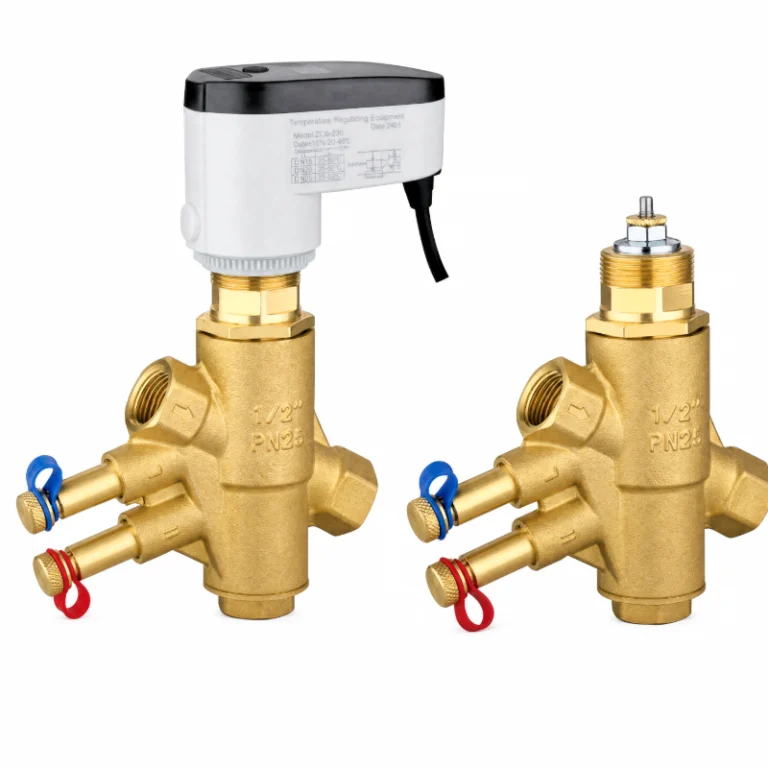
The GF-PICV-02 is a two-way pressure-independent control valve, DN15 to DN25, Kvs 1.0 to 3.0, with a thermoelectric or motorized actuator fitted on the body. It goes on fan coil, chilled beam and AHU branches, and on district cooling substations, one per terminal. A terminal balanced at handover drifts off its design flow by the afternoon, and the actuator keeps opening to make up the difference. The flow holds at the setting, and riser pressure stops deciding it.

GF-PICV-02 PICV valve body with 5-position mechanical preset dial, position 1 = minimum flow, position 5 = maximum flow
ParameterValue
SizeDN15, DN20, DN25 (G ½, G ¾, G 1)
Pressure RatingPN25
Working TemperatureLiquid up to 100 °C
Max. differential600 kPa
Kvs1.0 / 2.6 / 3.0 m³/h
Flow settings5 positions, 490 / 1000 / 1800 L/h at position 5

Working Principle

The diaphragm reads the differential across the orifice and balances it against a spring. When riser pressure climbs, the regulator closes and the differential stays put, so the flow follows the plug position alone.

Maximum flow is set on the scale with a wrench, in five positions. Position 5 is full open and 1 the minimum; the table gives 490, 1000 or 1800 L/h by size at position 5.

Thermoelectric actuator at 77 to 90 N, 45 or 70 seconds. Motorized at 100 to 150 N, 45 or 120 seconds, Modbus RS485 on request. Both run on 230 V or AC 24 V, IP65.

5-position mechanical flow setting dial of GF-PICV-02 PICV, with adjustment direction and three typical preset positions
Read the setting where the dial number lines up with the index mark on the body.

Flow Performance Data

DN15 · G ½″ — flow rate (L/h) at each dial position

ΔP (kPa)5 (max)4321 (min)
104203001707228
204903201957731
304903001957832
504803202008031
804803302008031
1004803302008031
1504703302007930
2004603201957828
3004503101807528
4004303201807226
5004103101807025
6004002801606624

DN20 · G ¾″ — flow rate (L/h) at each dial position

ΔP (kPa)5 (max)4321 (min)
1059052043032060
2080067058042080
3092074062046088
5098078065048098
801000800660480110
1001000800660470110
1501000790660480115
200970790650470115
300970770640460100
40093075062045088
50088072060044086
60084069059043083

DN25 · G 1″ — flow rate (L/h) at each dial position

ΔP (kPa)5 (max)4321 (min)
1074066047036060
20105091070050090
3012001000880640120
50155013001040800160
80180014501050860190
100180015001100880200
150180015001100900200
200180015501100900200
300165813831045830178
400180015001100900190
500175015001100900190
600170014501050870180

Dimensions & Kvs

DNConnection (R)SW (mm)H (mm)H1 (mm)L (mm)Kvs (m³/h)
15G ½''2611149.5691.0
20G ¾''3111149.5982.6
25G 1''37.511249.51063.0
GF-PICV-02 PICV general arrangement drawing with actuator, marking key dimensions and minimum 30 mm top clearance

Materials of Construction

Cutaway drawing of GF-PICV-02 PICV, highlighting the diaphragm-based pressure regulating mechanism with part number references
No.ComponentMaterialStandard
1Valve bodyCW617NEN 12164
2BonnetCW617NEN 12164
3Middle regulating seatPPS + 30% glass fibre
4DialABS
5Valve stemUNS S30400 / EN 1.4301
6Valve sleevePPS + GF30%
7Lower regulating seatPPS + GF30%
8SpringUNS S30400 / EN 1.4301
9O-ringEPDM
10Rubber diaphragmEPDM

Standard body material: brass CW617N (CuZn40Pb2; EN 12164 / EN 12165).

Other grades: HPb59-1 (GB/T 5231) and CW602N dezincification-resistant brass. Both are available on request and must be stated on the order. We do not substitute a different grade without your written approval.

Minimum order quantity: applies to all three grades.

Lead content: all three are leaded brass. CW617N carries 1.6–2.5% lead, and HPb59-1 carries 0.8–1.9%. For potable water, confirm the lead-leaching limits of the destination market before ordering.

Material certificate: EN 10204 3.1 on request. The grade stated on the certificate governs.

Actuator Options & Technical Data

ParameterThermoelectric actuatorMotorized actuator
Thrust77–90 N100–150 N
Travel time45 s (DN15, DN20), 70 s (DN25)45 s (DN15, DN20), 120 s (DN25)
Fail-safe travel time—4 s / 8 s
Power supply230 V AC, 50 Hz / 24 V AC, 50 Hz230 V AC, 50 Hz / 24 V AC, 50 Hz
Power—approx. 3 VA
Bus—Modbus RS-485 (on request)
Enclosure protectionIP65IP65
— = not applicable.

Typical Applications

One valve per terminal, on the return pipe where the run allows, horizontal or vertical with the actuator above the body, flow arrow downstream. A 0.5 mm filter ahead of the valve keeps the orifice clear, and about 30 mm of space above the body is needed to work on the actuator.

FAQs

What differential pressure does it need?

Each setting needs a minimum differential before it reaches its rated flow: 490 L/h on DN15 from 20 kPa, and 1000 L/h on DN20 or 1800 L/h on DN25 from 80 kPa. Below that the flow sits under the setting. The upper limit is 600 kPa.

How flat is the flow as the differential moves?

On DN15 at position 5 the table reads 480 to 490 L/h from 20 to 100 kPa, 460 at 200 kPa and 400 at 600 kPa. Flow falls as the differential climbs, so read the design point off the curve instead of the nominal figure.

Can the maximum flow be changed after commissioning?

Yes. The scale on the cartridge turns with a wrench, five positions, with the valve still in the line. Position 5 is full open and position 1 is the minimum.

Specifications

ParameterValue
Product TypePressure Independent Control Valve
SeriesGF-PICV-02
Body MaterialCW617N Brass
Nominal SizeDN 15–25
Pressure RatingPN 25
Flow Control Accuracy±10 %
Working Differential Pressure10–600 kPa
Maximum Fluid Temperatureup to 100 °C
Connections (female/female)G (ISO 228-1) · BSPT (ISO 7-1) · NPT
Flow Regulation5-position dial; DN15 max. 490, DN20 max. 1000, DN25 max. 1800 L/h
ActuatorThermal or motorized, on/off or modulating.

Models

PICV Valve Body Selection

TypeMaterialDNConnectionsKvs (m³/h)Weight (g)Code Number Inquiry
Brass 15 External thread ISO 228-1(BSPP) G ½'' 1.0 330 GF-PICV-02-15
Brass 20 External thread ISO 228-1(BSPP) G ¾'' 2.6 376 GF-PICV-02-20
Brass 25 External thread ISO 228-1(BSPP) G 1'' 3.0 510 GF-PICV-02-25
Brass 15 External thread ISO 228-1(BSPP) G ½'' 1.0 365 GF-PICV-02-15-A9
Brass 20 External thread ISO 228-1(BSPP) G ¾'' 2.6 411 GF-PICV-02-20-A9
Brass 25 External thread ISO 228-1(BSPP) G 1'' 3.0 545 GF-PICV-02-25-A9

Model Group 1

Material
Brass
DN
15
Connections
External thread ISO 228-1(BSPP) G ½''
Kvs (m³/h)
1.0
Weight (g)
330
Code Number
GF-PICV-02-15
Material
Brass
DN
20
Connections
External thread ISO 228-1(BSPP) G ¾''
Kvs (m³/h)
2.6
Weight (g)
376
Code Number
GF-PICV-02-20
Material
Brass
DN
25
Connections
External thread ISO 228-1(BSPP) G 1''
Kvs (m³/h)
3.0
Weight (g)
510
Code Number
GF-PICV-02-25

Model Group 2

Material
Brass
DN
15
Connections
External thread ISO 228-1(BSPP) G ½''
Kvs (m³/h)
1.0
Weight (g)
365
Code Number
GF-PICV-02-15-A9
Material
Brass
DN
20
Connections
External thread ISO 228-1(BSPP) G ¾''
Kvs (m³/h)
2.6
Weight (g)
411
Code Number
GF-PICV-02-20-A9
Material
Brass
DN
25
Connections
External thread ISO 228-1(BSPP) G 1''
Kvs (m³/h)
3.0
Weight (g)
545
Code Number
GF-PICV-02-25-A9

Electric Actuator Selection

TypeModelSpecificationsOutput SignalNominal Force (N)Weight (g) Inquiry
A9-0 - Input: 0–10 V DC (Default) / 2–10 V DC - Valve Type: NC (Default) / NO - Power Supply: 24 V AC/DC (−30% to +20%) - LCD Status Display - Control Type: Proportional Control No Output Signal 100 N / 150 N (Default) / 200N 35
A9-1 - Input: 0–10 V DC (Default) / 2–10 V DC - Valve Type: NC (Default) / NO - Power Supply: 24 V AC/DC (−30% to +20%) - LCD Status Display - Control Type: Proportional Control - Feedback: 0–10 V DC / 2–10 V DC 0–10 V DC (Default) / 2–10 V DC 100 N / 150 N (Default) / 200N 35
A9-2 - Modbus RTU - Valve Type: NC (Default) / NO - Power Supply: 24 V AC/DC (−30% to +20%) - LCD Status Display - Control Type: Proportional Control - Feedback: 0–10 V DC / 2–10 V DC 100 N / 150 N (Default) / 200N 35
A9-3 - Valve Type: NC (Default) / NO - Power Supply: 24 V AC/DC (−15% to +20%) - LED Status Indicator - Control Type: 3-Point Control No Output Signal 150 N (Default) / 200 N 35
A9-4 - Valve Type: NC (Default) / NO - Power Supply: 90–250 V AC/DC (−15% to +20%) - LED Status Indicator - Control Type: 3-Point Control No Output Signal 150 N (Default) / 200 N 35

Model Group 1

Model
A9-0
Specifications
- Input: 0–10 V DC (Default) / 2–10 V DC
- Valve Type: NC (Default) / NO
- Power Supply: 24 V AC/DC (−30% to +20%)
- LCD Status Display
- Control Type: Proportional Control
Output Signal
No Output Signal
Nominal Force (N)
100 N / 150 N (Default) / 200N
Weight (g)
35
Model
A9-1
Specifications
- Input: 0–10 V DC (Default) / 2–10 V DC
- Valve Type: NC (Default) / NO
- Power Supply: 24 V AC/DC (−30% to +20%)
- LCD Status Display
- Control Type: Proportional Control
- Feedback: 0–10 V DC / 2–10 V DC
Output Signal
0–10 V DC (Default) / 2–10 V DC
Nominal Force (N)
100 N / 150 N (Default) / 200N
Weight (g)
35
Model
A9-2
Specifications
- Modbus RTU
- Valve Type: NC (Default) / NO
- Power Supply: 24 V AC/DC (−30% to +20%)
- LCD Status Display
- Control Type: Proportional Control
- Feedback: 0–10 V DC / 2–10 V DC
Nominal Force (N)
100 N / 150 N (Default) / 200N
Weight (g)
35
Model
A9-3
Specifications
- Valve Type: NC (Default) / NO
- Power Supply: 24 V AC/DC (−15% to +20%)
- LED Status Indicator
- Control Type: 3-Point Control
Output Signal
No Output Signal
Nominal Force (N)
150 N (Default) / 200 N
Weight (g)
35
Model
A9-4
Specifications
- Valve Type: NC (Default) / NO
- Power Supply: 90–250 V AC/DC (−15% to +20%)
- LED Status Indicator
- Control Type: 3-Point Control
Output Signal
No Output Signal
Nominal Force (N)
150 N (Default) / 200 N
Weight (g)
35

Live Showcase

Product showcase materials are being prepared.

Documents

Technical documents are available upon request.

FAQ

Product-specific information is being prepared.